What is OSI Model ?
The OSI model is a logical and conceptual model that defines network communication used by systems open to interconnectio and communication with other systems .Charles
Bachman at Honeywell information system was the one to suggest the idea of the OSI model. But over time, it became quite famous with international recognition. The history of the OSI model dates back to the early 1970’s.
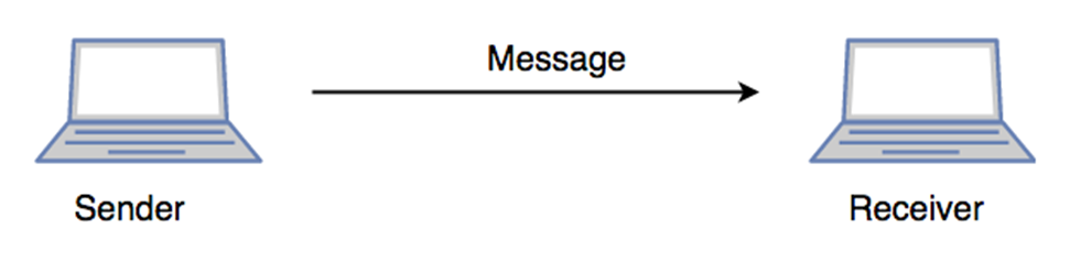
OSI model is a communication between one computer sofware to another computer software. The OSI model developed was ISO International Organization or Standardization. Its considered as architeture model of Inter-Computer Communication. OSI model has 7 layers .The entire communication has diveded into specific tasks. Therefor each layer has to perform indepented tasks.
Charactertics of OSI model :
Application Layer
Presentation Layer
Session Layer
Transport Layer
Network Layer
DataLink Layer
Physical Layer
The OSI model is diveded into two layer :
- Upper Layer
- Lower Layer
The Upper layer of the OSI model mainly deals with the application related issues, and they are implemented only in the software. The application layer is closes to the end user. Both the end user and the application layer interact with the software applicaion. Lower layer of the OSI model deals with the data transport issues. The data link layer and the physical layer are implemented in hardware and software.
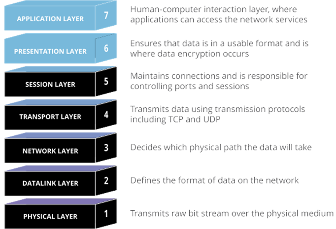
The 7 layers of OSI Model:
There are seven OSI layers. Each layer has different functions;
- Physical Layer
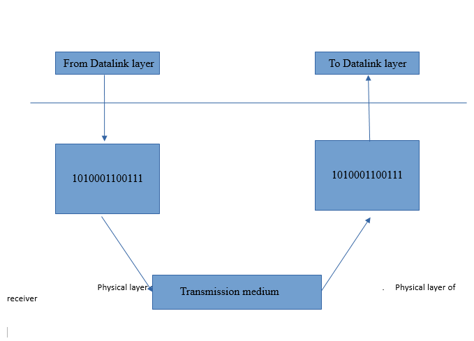
The lowest layer of the OSI model reference model is the physical layer. It is responsible for the actual physical connection between the devices. The physical layer contains information in the form of bits. It covert bits from electronics signals is physical layer. Ethernet,USB,etc…these hardware dives are included in the physical layer. The main functionality of the physical layer is to transmit the individual bits from one node to another node. It establish, maintain and deactivate the physical connections.
2. DataLink Layer
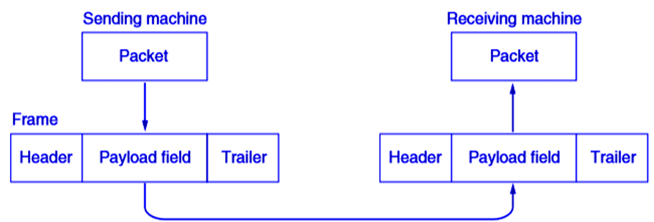
The data link layer, directly connected nodes are used to perform node-to-node data transfer where data is packaged into frames. The data link layer also corrects errors that may have occurred at the physical layer.When a packet arrives in a network, it is the responsibility of DLL to transmit it to the Host using its MAC address.
Data Link Layer is divided into two sublayers:
- Logical Link Control (LLC)
- Media Access Control (MAC)
The packet received from the Network layer is further divided into frames depending on the frame size of NIC(Network Interface Card). DLL also encapsulates Sender and Receiver’s MAC address in the header.
The Receiver’s MAC address is obtained by placing an ARP(Address Resolution Protocol) request onto the wire asking “Who has that IP address?” and the destination host will reply with its MAC address.
3. Network Layer
The network layer works for the transmission of data from one host to the other located in different networks. It also takes care of packet routing i.e. selection of the shortest path to transmit the packet, from the number of routes available. The sender & receiver’s IP addresses are placed in the header by the network layer.
The functions of the Network layer are :
- Routing: The network layer protocols determine which route is suitable from source to destination. This function of the network layer is known as routing.
- Logical Addressing: In order to identify each device on internetwork uniquely, the network layer defines an addressing scheme. The sender & receiver’s IP addresses are placed in the header by the network layer. Such an address distinguishes each device uniquely and universally.
4.Transaport Layer
This is the 4 layer of OSI model. This includes taking data from the session layer and breaking it up into chunks called segments before sending it to Network layer. The transport layer is also responsible for flow control and error control. Flow control determines an optimal speed of transmission to ensure that a sender with a fast connection doesn’t overcome a receiver with a slow connection. The transport layer performs error control on the receiving end by ensuring that the data received is complete, and requesting a retransmission if it isn’t. At receiver side Transport Layer reads the port number from its header and forwards the Data which it has received to the respective application. It also performs sequencing and reassembling of the segmented data. The transport layer is the decided to which services provided to user.
In Transport layer has used two protocols:
- TCP (Transmission control protocol)
- UDP (User datagram protocol)
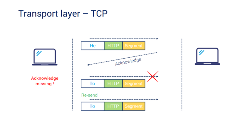
TCP is the Connection Oriented Protocol. It is standard protocol that allows to system communicate over the inter- net. It establish and maintain the connection between hosts. When a data sends over the TCP connection, then the TCP protocol divides the data into a smaller units known as segments. Each segments travel over the internet using multiple routes, and they arrives in different orders at the destination. The transmission control protocol reorders the packets in the correct order in the receiving end.
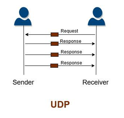
UDP is a Transport Layer protocol. It is an unreliable transport protocol as in this case receiver does not any acknowledgment when the packet is received, the sender does not wait for any acknowledgment. Therefore this makes protocol is unreliable
5.Session Layer
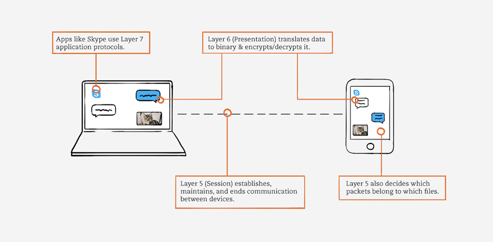
This is the fifth layer of the OSI model. The session layer controls the conversations between different computers. A session or connection between machines is set up, managed, and termined at layer 5. Session layer services also include authentication and reconnections. Based on the transport layer, session layer uses the services provided by the transport layer, enables applications to establish and maintain sessions and to synchronize sessions. The use of checkpoints by the session layer enables the communication session to resume communication from the checkpoint at the time of communication failure. This ability to send large files is extremely important.
- Session
The first responsibility is create session.
![]()
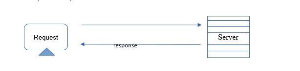
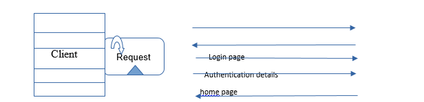
First the client sends a request to server to start a session, And the server to check which session is to provide to client then sends the response to client. We have already the server is do not provide sessions o client until it’s not verified, That is the our next service Authentication;
- Authentication
- Session Restoration
The session layer of the OSI model is responsible for session checkpoints and recovery. It allows information of different streams, perhaps originating from different sources, to be properly combined or synchronized.
An example usage of the session layer is session beans, which are only active as long as the session is active, and are deleted when the session is disconnected. Java developers can use them to store information about the user during a web session.
If any network issues or any error while download any media, the checkpoint will divide any media and create check points, One of the original and now most common means of application check pointing was a “save state” feature in interactive applications, in which the user of the application could save the state of all variables and other data to a storage medium at the time they were using it and either continue working, or exit the application and at a later time, restart the application and restore the saved state.
6. Presentation Layer
The presentation layer is layer 6 of the 7-layer Open Systems Interconnection (OSI) model. It is used to present data to the application layer (layer 7) in an accurate, well-defined and standardized format.
The presentation layer is responsible for the following:
- Data encryption/decryption
- Data compression
The presentation layer mainly translates data between the application layer and the network format. Data can be communicated in different formats via different sources. Thus, the presentation layer is responsible for integrating all formats into a standard format for efficient and effective communication. The presentation layer follows data programming structure schemes developed for different languages and provides the real-time syntax required for communication between two objects such as layers, systems or networks. The data format should be acceptable by the next layers; otherwise, the presentation layer may not perform correctly. Network devices or components used by the presentation layer include redirectors and gateways.
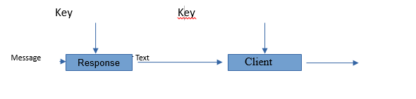
- Data encryption/decryption
Encryption and decryption of data communications are also commonly performed at the presentation layer. Here, encryption methods and keys are exchanged between the two communicating devices. Thus, only the sender and receiver can properly encode and decode data so it returns to a readable format.
- Data compression
Data compression is the function of presentation layer in OSI reference model. Compression is often used to maximize the use of bandwidth across a network or to optimize disk space when saving data.
There are two types of compression:
- Loss Compression
- Lossless Compression
Loss Compression:
Data compression is the function of presentation layer in OSI reference model. Compression is often used to maximize the use of bandwidth across a network or to optimize disk space when saving data.
Lossless Compression:
Lossless compression compresses the data in such a way that when data is decompressed it is exactly the same as it was before compression. There is no loss of data. A lossless compression is used to compress file data such as executable code, text files, and numeric data, because programs that process such file data cannot tolerate mistakes in the data. Lossless compression will typically not compress file as much as loss compression techniques and may take more processing power to accomplish the compression.
7. Application Layer
The application layer in the OSI model is the closest layer to the end user which means that the application layer and end user can interact directly with the software application. The application layer programs are based on client and servers. The application layer should not be thought of as an application as most people understand it. Instead, the application layer is a component within an application that controls the communication method to other devices. It’s an abstraction layer service that masks the rest of the application from the transmission process. The application layer relies on all the layers below it to complete its process. At this stage, the data, or the application, is presented in a visual form the user can understand.

Two types of software provide access to the network within the application layer: network-aware applications, such as email, and application-level services, such as file transfer or print spooling.
A few examples of application layer protocols are the Hyper Text Transfer Protocol(HTTP), File Transfer Protocol(FTP), Post Office Protocol(POP), Simple Mail Transfer Protocol(SMTP) and Domain Name System(DNS).